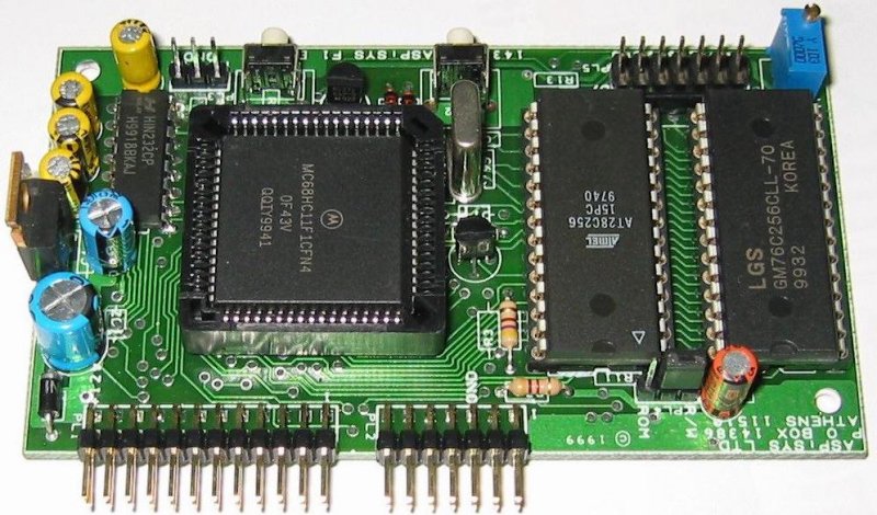


F1 Board features
|
MCU |
68HC11F1 (PLCC68). Socketed so it can be replaced easily, if needed. |
|
Crystal |
16MHz (4MHz bus) or 8MHz
(2MHz bus) upon request (no cost difference). |
|
Operating Modes |
Boot Mode (for re-programming it) and Expanded Mode (for normal operation). |
|
Mode
Selection |
Two conveniently placed push buttons for Reset in Expanded Mode or in Boot Mode. |
|
Internal RAM |
1024 Bytes mapped from $0000
to $03FF |
|
Internal EEPROM |
512 Bytes mapped at any 4KB page boundary (or completely disabled). |
|
External RAM |
32 KB mapped from $0000 to $7FFF
(The range $1000-$105F is by default occupied by internal MCU registers which are movable to any 4KB page boundary). Socketed. |
|
External
EEPROM |
32 KB mapped from $8000 to $FFFF (Software and Hardware write-protection). Socketed. |
|
A/D Channels |
Eight
8-bit A/D channels. |
|
SCI |
One SCI port (bypassing the MAX232 for 5V connections). |
|
SPI |
One SPI port. |
|
RS-232 Port |
On-board MAX232 (or compatible)
for direct connection to RS-232 of PC or other devices. |
|
LCD Port |
On-board 14-pin LCD port for L1672 or pin-compatible LCD.An LCD is optional. |
|
LCD
Contrast |
Adjustable with on-board trimmer. |
|
Reset Monitor |
On-board reset circuit/monitor. |
|
DIP connector |
DIP connector provides all otherwise
unused pins. |
|
Power Supply |
On-board voltage regulation allows you to connect anything between 9 to16 VDC. |
|
RPP |
Reverse-Polarity Protection
prevents damage if power is not properly connected. |
|
Schematics |
Full schematics and PCB layout are supplied as part of the board's documentation. |
|
Dimensions |
10.1cm (L)
[4 inches] x 5.8cm (W) [2 1/4 inches] x 2.5cm (H) [1 inch] |
|
Power Consumption |
37mA (42mA with LCD attached) under normal operation. |
|
Software |
Comes
with a CD with our assembler (ASM11), loader (B11), OS11 (S19 object only), soft manuals, examples! |
CLICK HERE TO SEE WHAT YOU GET
This
board is FULLY ASSEMBLED AND TESTED and is suitable both for development and low-volume production. We have been using it as the main
controller board in several of our custom-made products, but we feel it is also ideal for students, hobbyists, etc., and for any application
where frequent code changes may be required.
An on-board memory-mapped LCD port for direct connection of a L1672, or M1632, or any
pin-compatible LCD, is available for testing your LCD-related code. Or, connect a (short) flat ribbon cable to place the LCD away
from the controller board. Using a custom flat ribbon cable also allows you to use any LCD that is not necessarily pin-compatible
but uses the same 14 pins in a different order but with the same or compatible timing specifications. Included sample code will show
you how to use the LCD without losing any of the underlying RAM. The LCD's display contrast is manually adjustable via the on-board
variable resistor (trimmer). An LCD is optional.
The on-board MAX232 (or compatible) allows for RS-232 communications through a separate
3-pin port. The SCI pins are also available through the DIP connector bypassing the MAX232 for use as simple I/O pins, if needed.
The
board can be used stand-alone (e.g., flat on the its back for development), or perpendiculary inserted into a motherboard using
standard DIP connectors (for production, or integration to your design). All pins not used for memory access are available through
DIP connectors, except for /XIRQ which is reserved for future use. With the on-board voltage regulation you only need to supply from
9 to 17V DC.
Miscellaneous Notes:
- We intentionally used discrete components where possible in order to make it easier to modify or
repair if it ever needs to. Yet, we kept the size so small even SMT boards with all of the above features will envy this one.
- All
MCU pin tracks start off on the bottom layer only.
- The DIP connector header is spaced so that it is impossible to connect incorrectly
(idiot-proof).
- PCB silkscreen provides all needed information for quick reference.
DIP HEADER PINOUT
|
DIP Header No. |
PIN |
Description |
DIP
Header No. |
PIN |
Description |
|
PL1 |
1 |
PACC |
PL2 |
1 |
/PROG (Remote boot reset) |
|
|
2 |
OC2 |
|
2 |
XOUT |
|
|
3 |
OC3 |
|
3 |
/RESET |
|
|
4 |
OC4 |
|
4 |
/IRQ |
|
|
5 |
OC5 |
|
5 |
GND |
|
|
6 |
IC1 |
|
6 |
GND |
|
|
7 |
IC2 |
|
7 |
A/D
7 |
|
|
8 |
IC3 |
|
8 |
A/D 3 |
|
|
9 |
GND |
|
9 |
A/D 6 |
|
|
10 |
GND |
|
10 |
A/D 2 |
|
|
11 |
Port G0 |
|
11 |
A/D 5 |
|
|
12 |
Port G1 |
|
12 |
A/D 1 |
|
|
13 |
Port
G2 |
|
13 |
A/D 4 |
|
|
14 |
Port G3 |
|
14 |
A/D 0 |
|
|
15 |
CSIO2 |
|
|
|
|
|
16 |
CSIO1 |
|
|
|
|
|
17 |
SCI RX |
PL4 |
|
14-pin
standard LCD PORT |
|
|
18 |
SCI TX |
|
|
(L1672/M1632 or compatible) |
|
|
19 |
SPI SCK |
|
|
|
|
|
20 |
SPI SS |
PL3 |
1 |
RS232
TX |
|
|
21 |
SPI MOSI |
|
2 |
GND |
|
|
22 |
SPI MISO |
|
3 |
RS232 RX |
|
|
23 |
+Vdd |
|
|
|
|
|
24 |
+Vdd |
|
|
|
Software
included with this board
The board is accompanied by some very interesting software at no extra cost. This software effectively makes
it a complete F1 development system. Of course, you may also use whatever other tools you like. There are no compatibility issues
that would exclude the use of third-party compilers/assemblers/debuggers unless these products specifically limit themselves to certain
hardware configurations.
B11 is a downloader that lets you program your S19 files to either internal (EE)PROM or external memories
(RAM and Atmel-compatible EEPROM) on the fly. Just type B11 PROGNAME in most cases. You can also load multiple S19 files with a single
command. An option allows programming the CONFIG register only, or you can program it along with your program if the required CONFIG
byte value is part of your S19 file. A special option allows you to program internal EEPROM at any location without relocating your
S19 file. This is useful for 811E2 and F1 chips that can re-map their EEPROMs. All those cumbersome programming setup details are
hidden from the user, allowing you to concentrate on the job itself. It also works with the 16MHz (4MHz bus) version, just add the
option -M16 (which you can make permanent).
You may even interrupt the programming process midway and continue later without causing
any damage. Verification is automatic and concurrent, and possible errors are reported as they occur and optionally saved to an .ERR
file for further examination. The smart programming algorithm will only attempt to program locations that are different from the expected
value. This makes it possible to use B11 as a verifier. It also helps prolong the EEPROM's life since only different values
are rewritten. Also, because of the auto-verification, attempting to load over a programmed ROM (in read mode, write-protected or
without programming voltage) will report any mismatches as errors in programming! Examining the .ERR file will give you all the locations
where your code differs from the ROM image.
B11 will also work for other 68HC11 MCUs such as the E and A series both in single-chip
or expanded modes. No special talkers or commands for each different member! A universal built-in talker and communication protocol
accommodates all compatible members. Transparent Software Data Protection: B11 will automatically bypass the external EEPROM software
data protection (SDP) while programming it, but leave it enabled for normal use, no need to manually turn it on/off between run/programming
cycles. B11 will also identify the exact MCU type, even the secure versions (F1, E, or A series only, others may be added later).
A
separate talker utility allows you to quickly bulk-erase either the internal or external EEPROM, enable or disable the SDP feature
(for use with PCBug11 type debuggers that need to place breakpoints), all with one-letter commands via your RS-232 terminal.
ASM11 assembler
(an improved version of our Freeware ASM11) along with all its support utilities such as TERM, EXBIN, BSORT, etc. The current improvements
over the freeware version are:
1) The ability to export symbols to an .EXP file using EXP in place of EQU in your source for (non-local)
symbols that you want exported. The .EXP file can be used directly without editing as an INCLUDE file for other programs. This is
a very powerful feature that allows segmented compilation of larger programs (has some of the advantages of a linker).
2) Optimised
use of symbol table memory allows up to 60% more mapped source-lines or symbols.
3) Support for NoICE source-level debugging.
OS11 is
a library of additional ready-to-run routines. Part of this modular system provides a very simple to use pre-emptive (optionally settable
as co-operative) round-robin multitasker, a second SCI, as well as a command processor for making life easier when writing monitor-type
(or command-driven) programs. Possible future upgrades will be free to all registered owners, as they become available. Modular design
allows including only those modules needed plus adding your own custom modules for your specific application. For a more detailed
description, visit the OS11 page. Please note that only S19 object code is available to F1 Board clients. If you need
source, you need to purchase OS11 separately.
COMMAND is a simple small monitor-type program available in S19 format ready to load.
Source code is available. Work in monochrome or ANSI-color mode. COMMAND lets you perform some basic functions like examine or modify
memory, read the A/D channels, load S19 subroutines and execute them without setting up a whole application (you can also use the
available OS calls to do most things with minimum effort). Can be used to test independent subroutines before integrating into larger
application, for educational purposes where you only need to perform a certain function, or for test-driving complete applications.
It is also useful as an example of a complete application. For more information, visit the OS11 page.
We support what we sell
(both hardware and software).
This 68HCxx WebRing site owned by ASPiSYS Ltd..
[Previous Site | Next | Random | List All Sites | Join
Ring]